Abstract
Open-Source Framework

FluxDAgger: A Model-Decoupled DAgger Pipeline for Dual-Arm Robotic Manipulation

Ryan Hu1
1LimX Dynamics

Abstract

We present FluxDAgger, a model-decoupled DAgger pipeline designed for dual-arm robotic manipulation tasks. Unlike conventional DAgger implementations that tightly couple the policy model with the data collection process, FluxDAgger provides a universal framework that is compatible with arbitrary Vision-Language-Action (VLA) models and reward models. Our system features a modular ROS-based architecture with synchronized multi-camera observation, real-time teleoperation interfaces, and an interactive DAgger data collection workflow. The pipeline supports multiple operational modes including human demonstration collection, autonomous policy rollout with online human intervention, and reward-guided data filtering. We demonstrate the effectiveness of FluxDAgger on bimanual manipulation tasks using a dual 6-DOF robotic arm platform with synchronized camera views.

Demo

FluxDAgger System

Overall architecture and design details

FluxDAgger is our proposed human-in-the-loop DAgger pipeline, featuring a model-decoupled architecture compatible with arbitrary VLA and reward models. The system is organized as a set of ROS nodes including camera nodes, sync observation node, model inference node, DAgger controller, DAgger collector, and reward node — all communicating through standardized topic interfaces to enable seamless module replacement.

FluxDAgger System architecture

Figure 1. FluxDAgger system architecture: a model-decoupled pipeline compatible with arbitrary VLA and reward models.

Data Collection System

The original data collection system is built upon a dual-arm teleoperation platform consisting of cameras, a master arm (for human demonstration), and a slave arm (for robot execution). This baseline system provides the hardware foundation upon which FluxDAgger's human-in-the-loop DAgger pipeline is constructed.

Data Collection System overview

Figure 2. Overview of the original data collection system: camera, master arm, and slave arm components.

Hardware Modification

To adapt the original data collection hardware for the FluxDAgger pipeline, we modified the CAN communication topology from a shared bus to per-arm independent channels. In the original structure (Before), the master arm and slave arm were connected in series and shared one CAN bus branch through USB-to-CAN modules. In the modified structure (After), each arm is connected to an independent USB-to-CAN module, achieving one CAN interface per robotic arm so that each arm's master/slave mode can be configured independently.

Before (Original)
Original CAN bus control topology with shared CAN connection

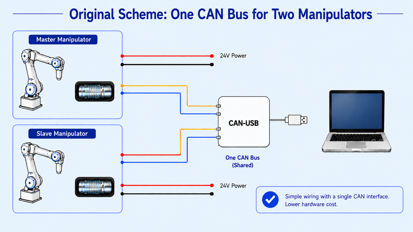
Master and slave arms are connected in series and share the same CAN bus branch.

After (FluxDAgger)
Modified CAN bus control topology with one USB-to-CAN interface per arm

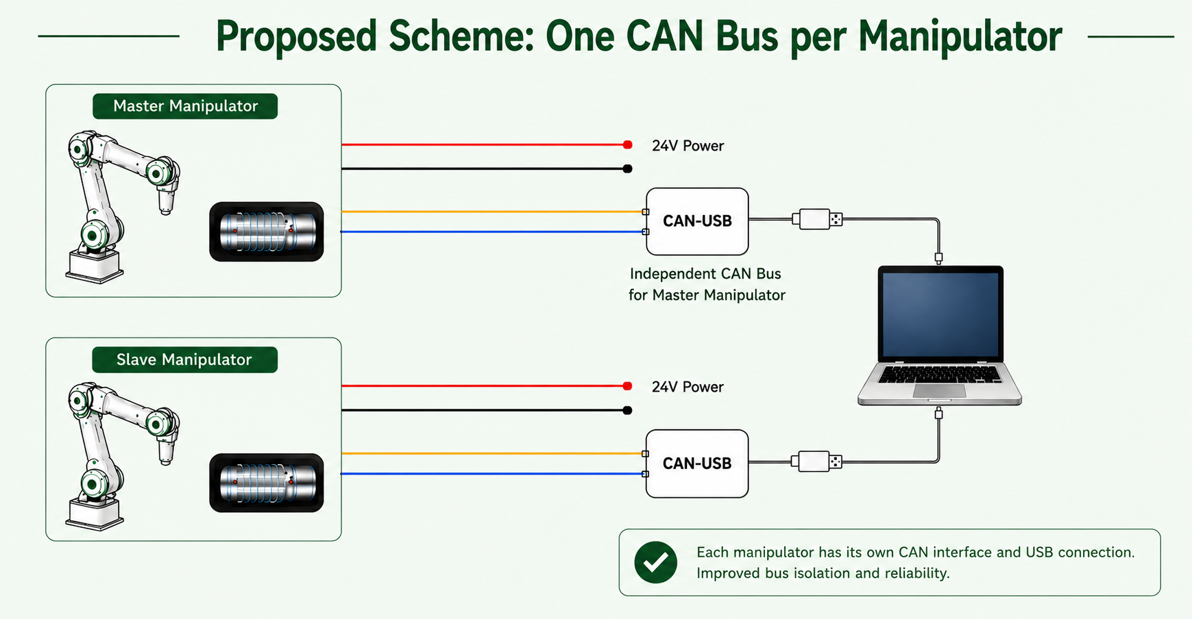
One USB-to-CAN module per arm: one CAN interface corresponds to one robotic arm.

Figure 3. Hardware modification from shared CAN-bus serial master-slave connection (Before) to per-arm independent USB-to-CAN mapping (After), i.e., one CAN interface per robotic arm.

Multi-Camera Synchronization

Precise temporal alignment across multiple camera streams is critical for consistent multi-view observations. FluxDAgger adopts the source data collection system's timestamp-based frame synchronization strategy: each camera maintains a frame buffer, and frames are aligned to a common sync timestamp. Frames arriving before the sync time are discarded (popleft if t < t1), ensuring all views correspond to the same physical moment. The right side shows the synchronized frame pair at timestamp t3 across all four camera views (front, head, left, right).

Multi-camera synchronization: sync frame pair mechanism

Figure 4. Multi-camera frame synchronization mechanism: timestamp-based alignment producing synchronized frame pairs across four camera views.

Online RL Data Flow

The online reinforcement learning data flow shows how FluxDAgger turns raw Aloha collection episodes into structured training assets. On the collection side, each episode is saved with sensor_index.json and Parquet trajectory data, then periodically synchronized to the data processing host via rsync. The processing host watches the incoming directory, parses new episodes, and exports multiple data views including sub-Parquet files, full-trajectory videos, segmented videos around human intervention periods, NumPy arrays, and LeRobot v2.1 format data.

When a batch reaches the configured number of episodes, FluxDAgger finalizes the batch by generating simple rewards, generating Qwen3 rewards, verifying the generated reward annotations, and uploading the complete processed package to Volcano Cloud TOS via rclone. This separates robot-side collection from heavier offline processing while keeping raw data, visualizations, reward labels, and training-format datasets synchronized.

Online RL data flow pipeline

Figure 5. Online RL data flow: episode collection, host-side parsing, reward generation and verification, and cloud upload.

Reward Visualize

During online DAgger data collection, the system captures synchronized observations from three camera perspectives (front, left, right) while simultaneously computing the reward signal via the reward model. The reward curve provides real-time feedback on task progress, enabling the DAgger controller to trigger human intervention when performance degrades.

Figure 6. Reward visualization: swipe across reward model renderings (Qwen3 Reward) during DAgger rollouts, showing synchronized multi-camera views with real-time reward curves.